
Getting a 2 x 16 LCD working
That's a strange heading - why wouldn't it work? Read on......
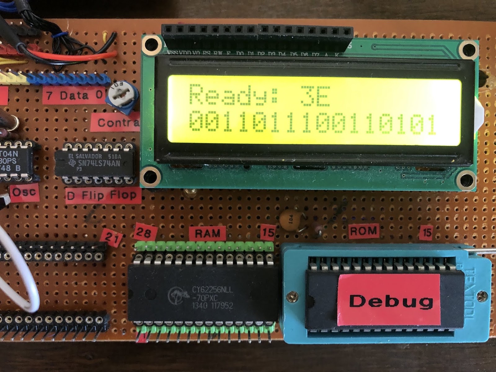
 The display I used is a cheap 2 line 16 character module using either the Hitachi HD44780 or a clone. It provides a lot of features but the data sheet is lengthy!
These cost a few pounds and come in a blue, white and yellow. Some offer an I2C interface but for this experiment I wanted to use the full 8 bits of the data bus so avoided those. There is also a software option to send data in two 4 bit nibbles but I only used 8 bit transfers.
Required connections are:
- Power
- Ground
- Adjustable voltage (use a potentiometer for any value between supply and ground) to set contrast
- Register select (RS)
- Read / write (RW)
- Enable (E)
- Data bus D0 - D7
Objectives
- To display ASCII text messages on both line 1 and line 2
- To track character position in software and be able to correctly position characters anywhere on the display
This was to be the first way of observing the system running - previously I had used an Arduino Mega to monitor the address and data bus but that limited the clock to hundreds of hertz (to avoid the Arduino not being able to read fast enough)
Approach
My starting point was a 65C02 running at 1MHz with 32k RAM and 8k ROM. Nothing else - no input or output devices. To run a new program required that it be flashed to ROM externally and re-fitted to the system. The only devices connected to the data bus were the ROM and RAM.
Address decoding and the provision of an 'Enable' (E) pulse was done like this:

RW from 6502
E = Enable. Pulse high to instruct the HD44780 to latch the data (if writing to it) or to present data on the address bus (if reading)
Data bus initially connected directly to 65C02, ROM and RAM
Data bus initially connected directly to 65C02, ROM and RAM
Writing to the display involves a few steps:
- initialise:
- set data width (4 or 8 bits), 2 lines and character size (5 x 8 dots)
- set entry mode - cursor can move left or right and display can shift or be fixed
- turn display on, select cursor style
- clear display and return cursor to home (top left)
- writing data
- send characters to display one by one
- reposition next character position if not the natural one to the right
IMPORTANT: after each write to the LCD registers (both command and data) there is a time delay while it is executed - new data or commands will be ignored until completion. My first fix was to insert a delay loop taking about 2mS after each command. The data sheet provides timings for each command so it is possible to shorten this for many commands.
A much better approach is to poll the LCD 'BUSY" flag which is bit 7 of the command register which is set until the LCD is ready to receive again then is cleared.
There are reports from other experimenters that the first step to initialise the LCD should be carried out THREE times although I found once worked fine. In the end I send the command to set data width, lines and character size three times - why not? This command can only be used after a power on reset so resetting the 6502 will not reset the LCD.
Assembler Code
Here is some assembler code useful for testing:
https://gist.github.com/robinharris/d4a5f9db8b90d20fcb73255de9b7bb06
This is a GitHub gist so can be viewed or downloaded to run.
Results
Disappointing - mostly nothing on the display. Occasionally a few random characters. After lots of power on resets only a few characters appeared and it looked at first to be an intermittent connection. That proved not to be the case so the next step was to investigate the control signals - RW, E and RS. All looked ok on the oscilloscope so I experimented with lengthening the E pulse and delaying the E pulse in case the data lines were not settled. I was clutching at straws!
Next I went back to slow / single stepping with a Ben Eater design clock and monitored the address and data bus with an Arduino Mega. The 6502 reset sequence went ok, but after a few steps the data bus was not as expected and this included address data so quickly the program counter leapt around. At first it looked like the address bus was implicated but it became clear that incorrect addresses were generated by incorrect data on the data bus.
After a lot of time going crazy I removed the LCD and single stepped - everything worked as expected. Adding the LCD module brought the problems back. I tried a different LCD module in case it was faulty - same results.
I tried both modules with an Arduino UNO writing discrete commands to copy the 6502 instructions and they both worked fine.
 |
| 74HC245 under LCD |
At that point I had no more ideas and was reading around bus pull ups, bus termination and stuff I had no clue about. Somewhere in that I saw a SBC design that used 74HC245 octal bus transceivers, apparently as a 'belt and braces' precaution. From that came a guess that maybe I could isolate the LCD from the ROM, RAM and 6502 with one of these devices so I ordered some.
With the bus transceiver installed between the native data bus and the LCD everything worked fine! That was a surprise, but sure enough, the results were reproducible - bypassing the 245 brought all the problems back.
I still do not understand why the problem occurred or why the bus transceiver fixed it but it worked.
Another experimenter has reported the same findings and used the same solution.
The issue gets more puzzling: after running with the LCD separated from the 6502, ROM & RAM by the transceiver for a while, a new board layout was required to add a 6522 VIA. Based on the above experience, I decided to use transceivers on both the address and data buses. Others more knowledgable than me suggested these should not be necessary with a WDC65C02. But I included them and the system worked fine.
One final experiment then - replace the data bus transceiver with wire links. Does the system still work - all the strife getting the LCD working suggests it would not.....
But it does😮.
I really don't know why, but these tests suggest there may have been layout issues with version 1 board and nothing intrinsic to the module.
Conclusions
- Cheap LCD modules work fine in a 6502 system
- The WDC65C02 does not need bus transceivers for small layouts at least
- Sometimes weird things happen that is impossible to explain
- Experimenting is fun and a great way to learn
- There is more to be learn from problems than instant success
Parts List
- 16 x 2 line LCD module
- 10k potentiometer
- 74HC245 octal bus transceiver (may not be required!)
- 74HC00 quad NAND gate
- 74HC04 hex inverter
Comments
Post a Comment