
Power & Reset Module

At the beginning of my 65C02 project the power supply was 5V taken from an Arduino Mega! Reset was a push button and pull up resistor on the RESET line. Couldn't have been more basic but it did work - mostly. As I read more, it became clear that the reset process should be more predictable (i.e. no key bounce). Also my initial setup required a manual reset at power on because there was no automatic mechanism to holding reset low.
Objectives
- 5V regulated supply to the complete 65C02 system from a 'wall wart'
- Auto reset on power up
- Manual reset that is consistent
- 8 - 24V input
- LED indicators
Approach
Voltage supervisors provide the required functionality of auto-reset and predictable manual reset. An adjustable step down buck converter will provide 5V at 1A from an input voltage of 6 - 60V. A simple circuit was designed:

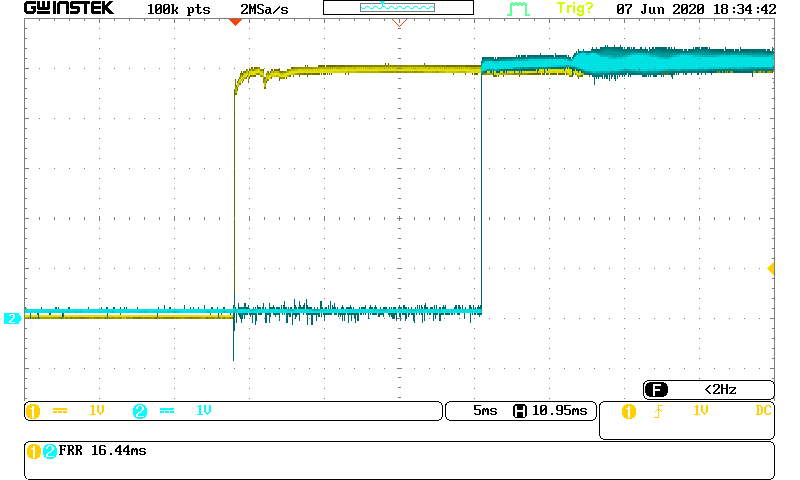
 This circuit provides a delay on RESET of 16.4mS. The image right is the oscilloscope trace - yellow is the 5V rail and blue is the REST line. The measured delay is shown bottom left.
 A manual reset is provided by a push button on the RESETIN line of the TL7705. This line is normally held high by the pull up resistor but when the button is pressed it goes low to initiate a reset. The duration of the low pulse on RESET is 158mS with the component values shown. The oscilloscope trace left shows the actual measurement.

When setting the output voltage of the converter set it up with a load roughly the same as I expect them to provide in circuit (resistors of a suitable rating) as the no-load regulation is not great.
I used a TL7705 voltage supervisor because there were a couple on eBay for a low price but there are a number of alternatives that provide more or less the same features. They all monitor the input voltage and as the voltage on the sense line passes 4.5V a delay starts with RESET held low. The TL7705 actually provides both a positive and negative edge - for the 65C02 we use a negative one of course. The negative reset line is pulled high by a 10K resistor when not active and the positive one is pulled low by another 10K resistor.
 This circuit provides a delay on RESET of 16.4mS. The image right is the oscilloscope trace - yellow is the 5V rail and blue is the REST line. The measured delay is shown bottom left.
 A manual reset is provided by a push button on the RESETIN line of the TL7705. This line is normally held high by the pull up resistor but when the button is pressed it goes low to initiate a reset. The duration of the low pulse on RESET is 158mS with the component values shown. The oscilloscope trace left shows the actual measurement.
There are two capacitors on the 5V line out of the converter to reduce any ripple or noise (10uF and 100nF)
A red LED indicates that there is 5V available. A green one shows that the TL7705 and the 65C02 system is powered up.
I made a small frame to hold the 2.1mm barrel connector (power in), the voltage converter and the prototype board with the other components on.
 |
| Home made 'box' |
 |
| Voltage converter on its side on left |
Conclusions
- The voltage converter works fine
- LEDs to monitor status look cool and are useful
- TL7705 does it job - no more manual resets on power on
- Manual reset works flawlessly
- The time between power on and RESET going high is easily varied by changing one capacitor
Components
 |
| 4.5 - 60V Step down adjustable voltage converter |
- Adjustable voltage converter (up to 20V input, output adjusted to 5V, 1A)
- TL7705 voltage supervisor (there are several other types)
- 2 x LED
- Latching push button switch (on / off)
- Resistors - 2 x 470R, 3 x 10K
- Capacitors - 10uf, 2 x 100nF, 1uF
- Mains power adaptor (wall wart) 8 - 15V output
 |
| TL7705 Voltage supervisor |
Comments
Post a Comment